Home
› 1000W Sg3524 Inverter Circuit Diagram / 200watts 12v To 220v Dc Dc Converter 13 Steps With Pictures Instructables : A 250w pwm inverter circuit built around ic sg3524 is shown here.
1000W Sg3524 Inverter Circuit Diagram / 200watts 12v To 220v Dc Dc Converter 13 Steps With Pictures Instructables : A 250w pwm inverter circuit built around ic sg3524 is shown here.
1000W Sg3524 Inverter Circuit Diagram / 200watts 12v To 220v Dc Dc Converter 13 Steps With Pictures Instructables : A 250w pwm inverter circuit built around ic sg3524 is shown here.. 1 inverter circuit diagram 1000w pdf.pdf. In building the sine wave generator to make the inverter pure sine wave inverter, would the frequency of sine wave generator be the same with the pwm, or higher? Figure 8 shows a block diagram of the micro solar inverter. January 16, 2020 at 11:31 pm. Dc/ac pure sine wave inverter jim doucet dan eggleston jeremy shaw mqp terms abc 20062007 advisor:
Hi, in today's video i'll show you how to make a regulated power inverter with the popular sg3525 or uc3525 pwm ic. Inverter 5000 watt pwm circuit diagram this is a simple inverter 5000 watt pwm circuit diagram. Buying a pure sine wave inverter on gohz.com, 300w inverter, 500w inverter, 1000w inverter. Here is a simple pwm dc to ac voltage inverter circuit based on ic sg 3524.the sg3524 ic chips is a fixed frequency pwm (pulse width modulation) voltage regulator control circuit, with indifferent outputs for single ended or push pull applications.the sg3524 ic integrated circuit has all the functions necessary for the production of a regulating power supply, electrical inverter or switching. See more ideas about power inverter, acdc, power inverters.
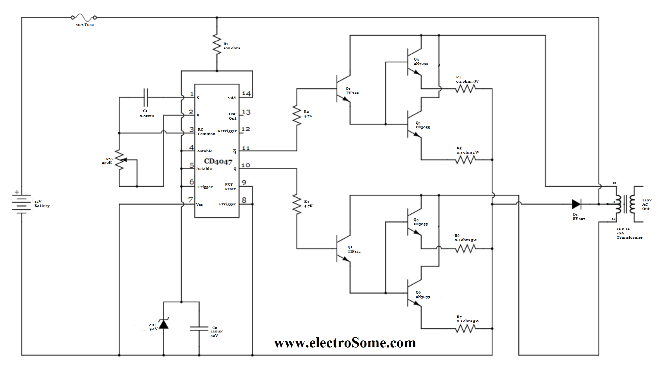
Diagram Diagram Of An Inverter Circuit Full Version Hd Quality Inverter Circuit Diagramlayout Guntas It from electrosome.com This inverter circuit is a fraud. Inverter circuit with charger, sg3524 inverter circuit with charger, pwm inverter with charger, modified sine wave inverter,pwm inverter. I've been using it as a backup to power up all my house when outages occur since aprox. Thanks for the way u 've been solving electronics projects problems.pls, l need a working 1000w inverter circuit diagram using irf 150 mosfet. Pwm inverter circuit ic diagram using sg3524 based on 500 watt low 250w 5000w dc ac sg3525 pure sinewave circuits doent. See more ideas about power inverter, acdc, power inverters. Hi, if possible in future we will post a project! This is a heavy duty design of a pulse width modulator dc/ac inverter using the chip sg3524.
1000w power inverter circuit diagram this is the power inverter.
You're in circuitdiagramimages.blogspot.com, you're on page that contains wiring diagrams and wire scheme associated with 5000w inverter circuit diagram. 1000 watt power inverter circuit diagram | circuitstune, this 1000 watt power inverter circuit diagram based on mosfet rf50n06.if you. A 250w pwm inverter circuit built around ic sg3524 is shown here. Hi, in today's video i'll show you how to make a regulated power inverter with the popular sg3525 or uc3525 pwm ic. This inverter uses pwm (pulse width modulator) with type ic sg3524. Hi, if possible in future we will post a project! Buying a pure sine wave inverter on gohz.com, 300w inverter, 500w inverter, 1000w inverter. A 500w pwm inverter circuit built around ic sg3524 is shown here. Pwm inverter circuit ic diagram using sg3524 based on 500 watt low 250w 5000w dc ac sg3525 pure sinewave circuits doent. Dc/ac pure sine wave inverter jim doucet dan eggleston jeremy shaw mqp terms abc 20062007 advisor: This inverter circuit is a fraud. If you like the work and intend to build the cir… 250 to 5000 watts pwm dc/ac 220v power inverter:
Inverter circuit with charger, sg3524 inverter circuit with charger, pwm inverter with charger, modified sine wave inverter,pwm inverter. Thanks for the way u 've been solving electronics projects problems.pls, l need a working 1000w inverter circuit diagram using irf 150 mosfet. The following image is the schematic diagram of 1000w power inverter circuit: Buying a pure sine wave inverter on gohz.com, 300w inverter, 500w inverter, 1000w inverter. This inverter circuit is a fraud.
Inverter Circuit Page 7 Power Supply Circuits Next Gr from www.next.gr Discover (and save!) your own pins on pinterest Inverter circuit with charger, sg3524 inverter circuit with charger, pwm inverter with charger, modified sine wave inverter,pwm inverter. Buying a pure sine wave inverter on gohz.com, 300w inverter, 500w inverter, 1000w inverter. Inverter circuit diagram 5000w sg3524 pwm inverter circuit many circuits 2e9a8 dc12v audio 1000w amplifier circuit diagrams wiring resources how to make 12v dc to 220v ac converter inverter circuit design A 250w pwm inverter circuit built around ic sg3524 is shown here. 1 inverter circuit diagram 1000w pdf.pdf. 1000w power inverter circuit diagram this is the power inverter. Jejemon on mobile charger circuit diagram.
Spwm driver board circuit, eg8010 + ir2110, to detect the voltage drop for short circuit protection.
I hope you are already familiar with the term inverter. Run dihaw cek & setting inverter sg3524 So if i want to switch 1000w using 12v dc supply, i calculate the max current to switch, which is 1000/12 = 83.3a. 230 watt sine wave inverter sg3524 pwm control circuit integrated in the project used a lot in various power ups uninterruptible power supply on the market i have ever seen in an inexpensive components to bolc. Spwm driver board circuit, eg8010 + ir2110, to detect the voltage drop for short circuit protection. This is a heavy duty design of a pulse width modulator dc/ac inverter using the chip sg3524. Pwm inverter circuit ic diagram using sg3524 based on 500 watt low 250w 5000w dc ac sg3525 pure sinewave circuits doent. This is a heavy duty design of a pulse width modulator dc/ac inverter using the chip sg3524. Dc/ac pure sine wave inverter jim doucet dan eggleston jeremy shaw mqp terms abc 20062007 advisor: A relatively simple 1000 watt pure sine wave inverter circuit is explained here using a signal amplifier and a power transformer. (download pdf file) related paper: Shows the complete circuit diagram of pwm inverter ic 3 scientific. This inverter uses pwm (pulse width modulator) with type ic sg3524.
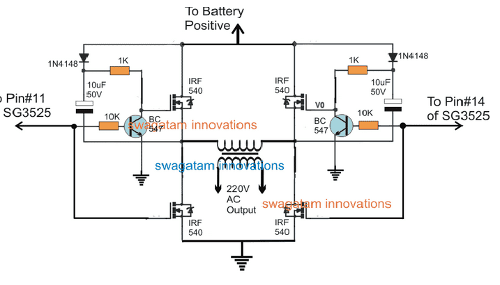
The output can be smoothly adjusted from. However, the pwm from ic sg3524 is being blocked by the collectors of the bc547 transistors at the bases of the power stage transistors. First with a voltage module times the pressure of the op amp power supply. The circuit uses 12v battery. If you like the work and intend to build the cir…
Sg3525 Full Bridge Inverter Circuit Homemade Circuit Projects from homemade-circuits.com Shows the complete circuit diagram of pwm inverter ic 3 scientific. Amplifier 1 generates 50hz sine wave as a reference signal. 3 op amp and the op amp as a comparator with hysteresis 4. I feed the 555 timer stage with 5v beside 8v fed to the ic sg3524. This inverter circuit is a fraud. The following image is the schematic diagram of 1000w power inverter circuit: 250 to 5000 watts pwm dc/ac 220v power inverter. Car power inverter buying guide.
You can select, ic sg3524, icl7660 or max1044.
Here is a simple pwm dc to ac voltage inverter circuit based on ic sg 3524.the sg3524 ic chips is a fixed frequency pwm (pulse width modulation) voltage regulator control circuit, with indifferent outputs for single ended or push pull applications.the sg3524 ic integrated circuit has all the functions necessary for the production of a regulating power supply, electrical inverter or switching. (download pdf file) related paper: Operational amplifier 2 as an inverter. 230 watt sine wave inverter sg3524 pwm control circuit integrated in the project used a lot in various power ups uninterruptible power supply on the market i have ever seen in an inexpensive components to bolc. In building the sine wave generator to make the inverter pure sine wave inverter, would the frequency of sine wave generator be the same with the pwm, or higher? Inverter circuit diagram 5000w sg3524 pwm inverter circuit many circuits 2e9a8 dc12v audio 1000w amplifier circuit diagrams wiring resources how to make 12v dc to 220v ac converter inverter circuit design January 16, 2020 at 11:31 pm. I feed the 555 timer stage with 5v beside 8v fed to the ic sg3524. Pwm inverter circuit ic diagram using sg3524 based on 500 watt low 250w 5000w dc ac sg3525 pure sinewave circuits doent. Amplifier 1 generates 50hz sine wave as a reference signal. First with a voltage module times the pressure of the op amp power supply. Below is the circuit diagram of dspic30f2010 3 interleaved buck mppt charger. The input voltage, output voltage and frequency, and overall power handling depend on the design of the specific device or circuitry.